1. Design Methodology for Centrifuge Pump
 |
 |
|
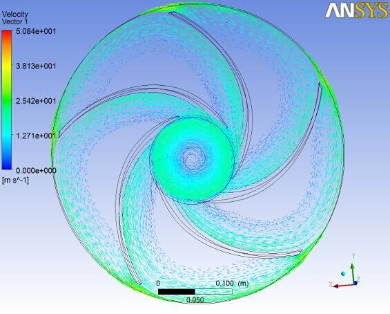
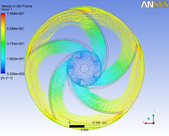
(a) Absolute Velocity Sector Diagram
|
(b) Relative Velocity Sector Diagram
|
|
Fig 1: Flow Vector Diagram in Designed Impellor
|
 |
 |
|
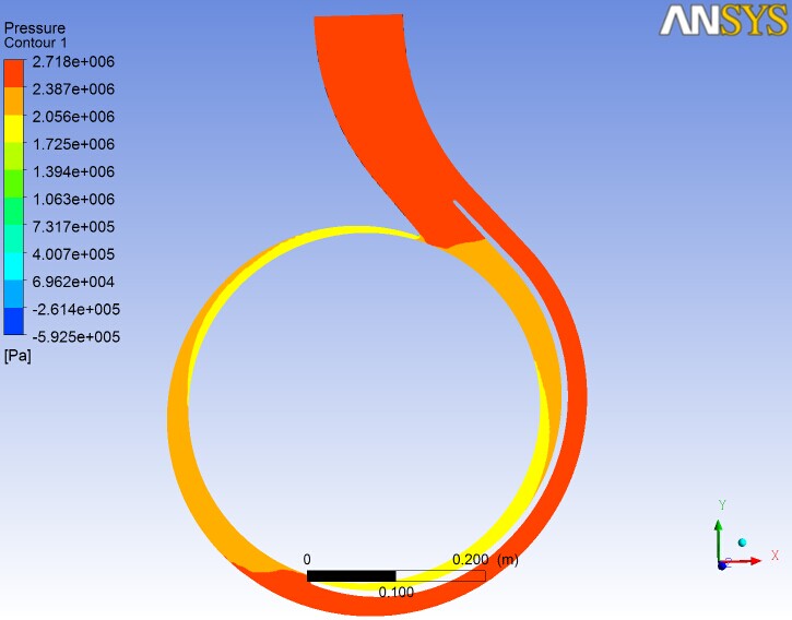
(a) Mid Section of Static Pressure Diagram of Volute |
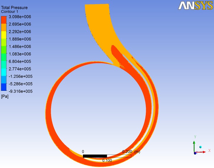
(b) Mid Section of Total Pressure Diagram of Volute
|
|
Fig 2: Diagram of Static Pressure and Total Pressure of Designed Volute |
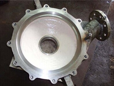
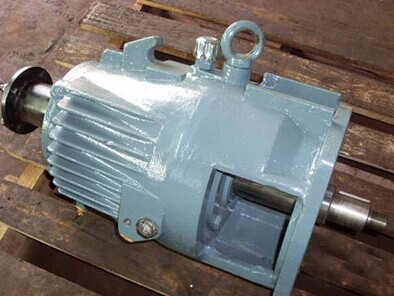
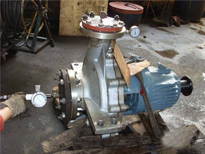
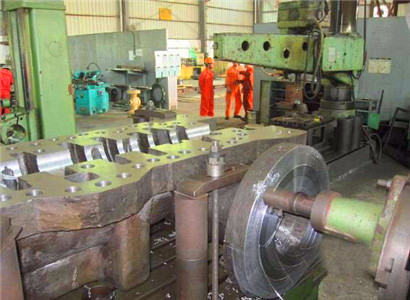
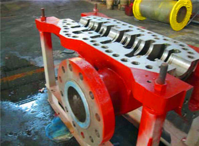
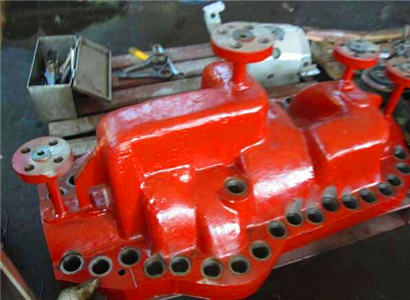
Single stage centrifuge pump:Moudle: 4HPX15A Flow Rate: 200m3/hr,Rotating Speed: 3583rpm, Power: 225KW, Range of lift: 278—294m. CCS Certified.2、Pump Manufacturing:
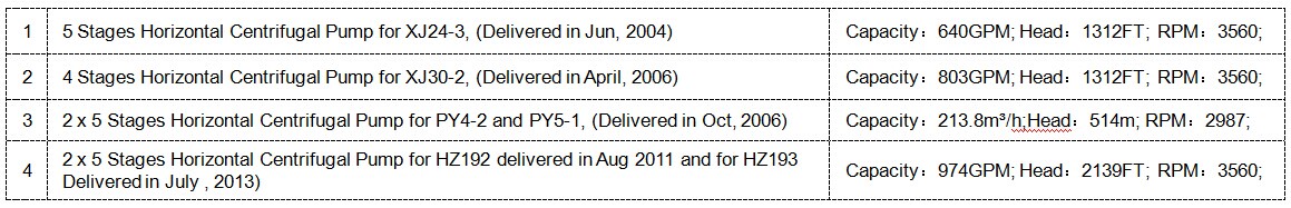
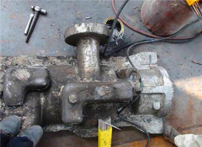
Tracked well operating Multi-Stage Pumps manufacture by us:
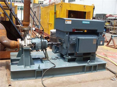
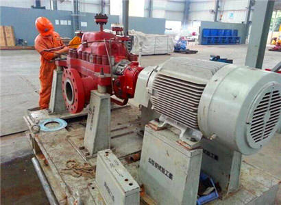
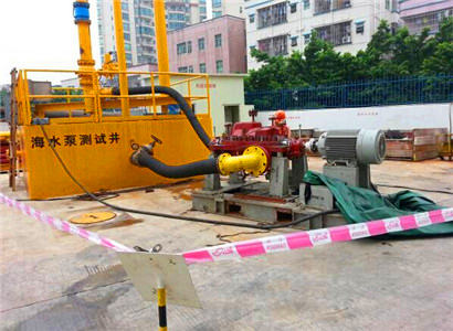
3. Transfer Centrifugal Pump for subsea pipeline preheat on XJ24-3 and P-2407, Anping Project
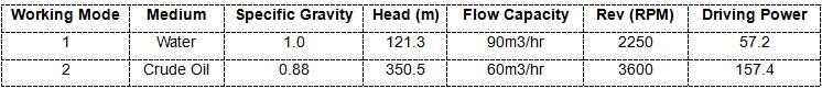
Pump Performance Data:
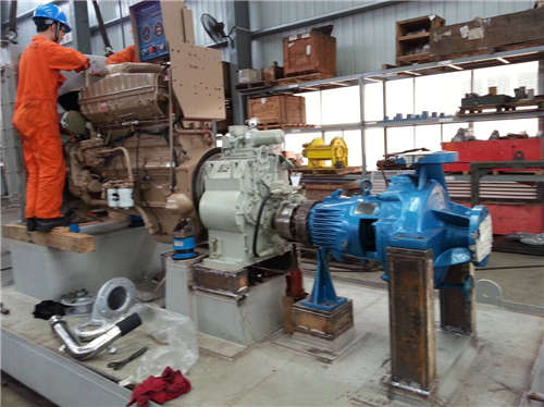
Pump Skid Manufacture
Skid and pump Design, manufacture, testing, CSS Certify, and FAT; Diesel Engine Driven, with transmission box, API Standard.
 |
|
Pump Skid for XJ24-3 and P-2407, Anping Project |
4. Anchor Weight Manufacture for POC
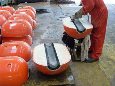
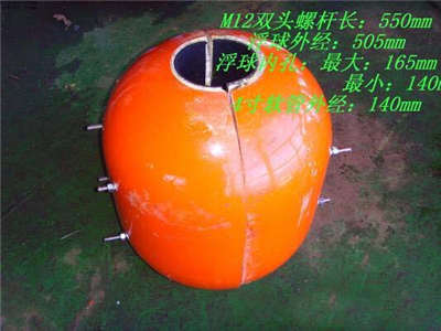
5. Offloading Hose Floating Buoy Manufacture:
 |
 |
|
Fabrication Process for Floating Buoy |
Offloading Hose Floating Buoy
|
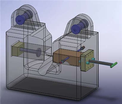
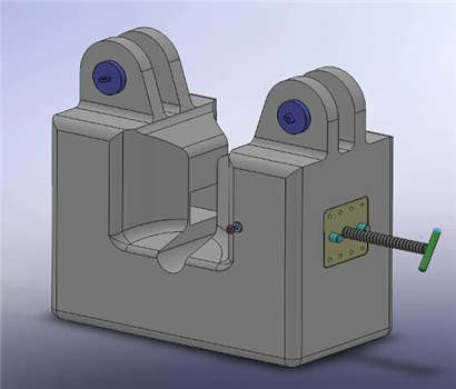
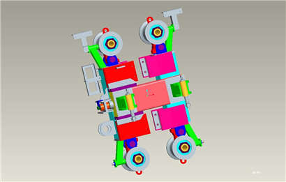
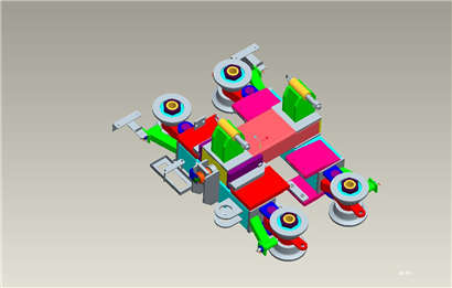
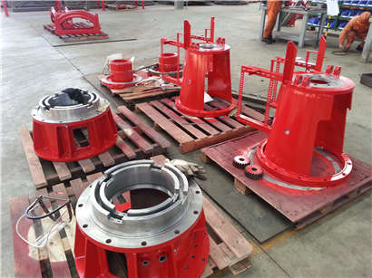
6. Drilling Top Driver Guide Dolly Farbication
 |
 |
|
3D View of Guide Dolly |
 |
 |
|
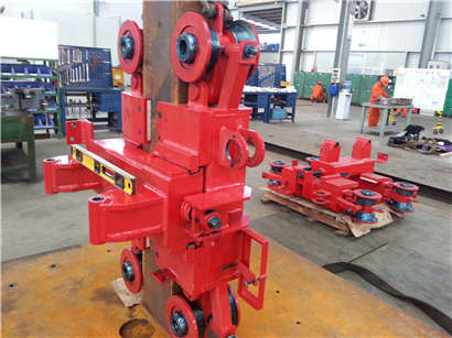
Guide Dolly Assembly |
|
 |
 |
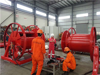
|
Hydrualic Hose Reel Test |
|
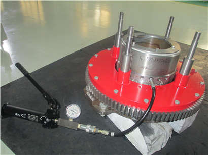 |
 |
|
Hydrostatic Test |
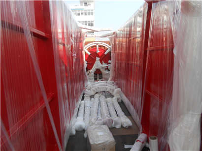
Pack & Delivery |